📚 Assignment 8 CMPE2250: SPI DAC (MCP4812)
📋 Overview
-
In this ICA you will use the externally connected SPI DAC to generate five different waveforms.
-
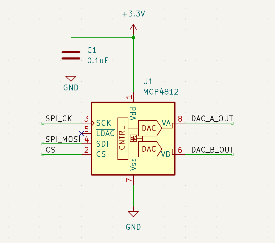
Begin with the DAC circuit as shown.
-
Create a program that will test various values on the SPI DAC and ensure that the expected voltage level is observed on each DAC channel using the AD2.
1️⃣ Part A - Main Functionality
- Use 4 buttons from the button board that will cause a different waveform to be generated. When each switch is pressed the associated waveform will appear on the DAC outputs:
| Switch | Waveform |
|---|---|
| SW1 | Sawtooth |
| SW2 | Offset Cosine |
| SW3 | Triangle |
| SW4 | ADC Follower |
DIsplay on Tera Term (and/or LCD if working) “Function Generator” on the first line, and the type of waveform being generated on the second.
- Upon reset your application will start with the triangle waveform.
- All output will appear on DAC channel A, with a gain of 2x.
- All output will appear on DAC channel B, inverted, with a gain of 1x.
The DAC datasheet can be found here:
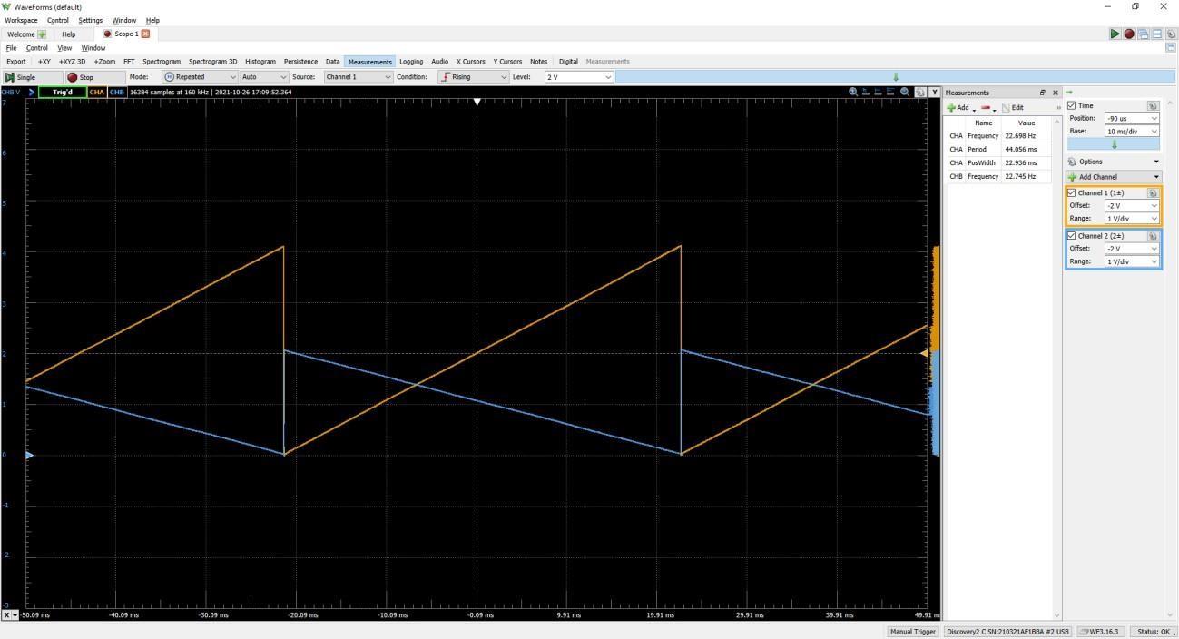
Sawtooth
- The sawtooth waveform will ramp up one count per main loop pass and wrap back to zero when the max value is reached.
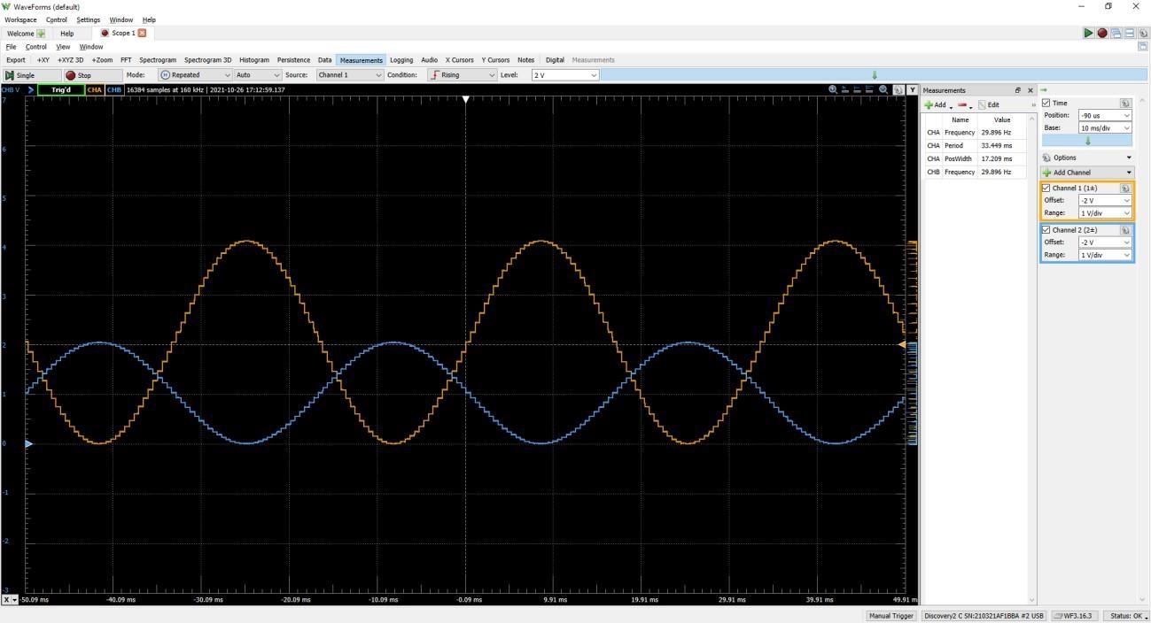
Offset Cosine
- The offset cosine waveform will cycle through an angle of zero to 2π, in steps of π/32. You will need to offset the cosine values so that they are all positive, and scale them to the entire range of the DAC.
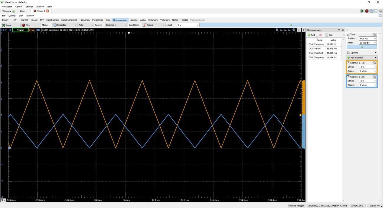
Triangle
- The triangle waveform will ramp up and down, without adjacent duplicate values, through the full DAC range.
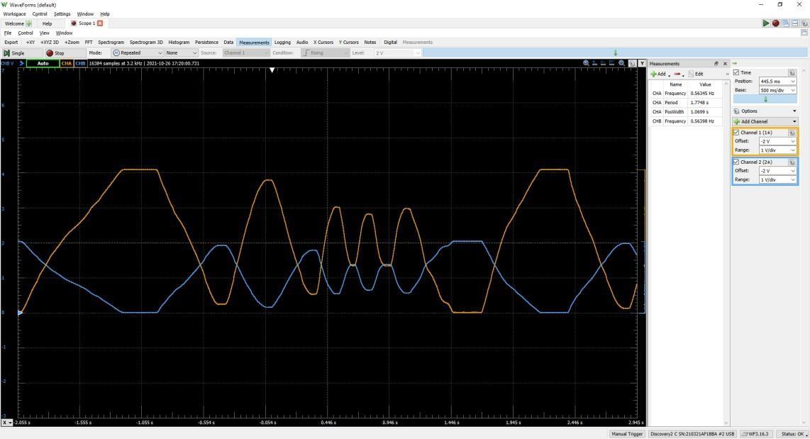
ADC Follower
- The ADC Follower waveform will replicate samples from the ADC. When studying the output on the AD2 for this part, ensure that the mode is ‘None’ for triggering, as the arbitrary input will not be suitable for triggering repeated display.