📚 CMPE1250: Alternate Functions
🎯 Learning Objectives
- Understand the purpose of alternate functions in STM32 GPIO pins.
- Learn how to use AFRL and AFRH registers to configure alternate functions.
- Practice configuring peripherals like UART, SPI, or TIM using GPIO alternate functions.
1️⃣ What Are Alternate Functions?
- GPIO pins on STM32 microcontrollers can serve multiple roles:
- Input/Output (default)
- Alternate Function (AF): connects the pin to internal peripherals like UART, SPI, I2C, TIM, etc.
- Think of each pin as a multi-tool—you choose the tool (function) by setting the right bits in the AFRL/AFRH registers.
2️⃣AFRL vs AFRH: Register Layout
Each GPIO pin has a 4-bit field to select its alternate function (AF0 to AF15) (DS CH4, Table 13 - Table 17).
| Register | Pins Covered | Bits per Pin | Total Bits |
|---|---|---|---|
| AFRL | 0–7 | 4 | 32 |
| AFRH | 8–15 | 4 | 32 |
3️⃣ Example: Configuring PA9 for USART1_TX (AF1) and PA10 USART1_RX (AF1)
We can find these details in the Datasheet CH4, Table 13.
Step-by-step:
- Enable GPIOA clock:
RCC->IOPENR |= RCC_IOPENR_GPIOAEN;
- Set PA9 and PA10 to Alternate Function mode:
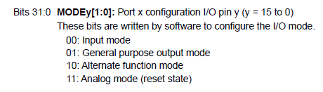
  GPIOA->MODER &= ~(0x3 << (9 * 2));      // Clear MODER9
  GPIOA->MODER |=  (0x2 << (9 * 2));      // Set MODER9 to '10b' (AF mode)

  GPIOA->MODER &= ~(0x3 << (10 * 2));      // Clear MODER10
  GPIOA->MODER |=  (0x2 << (10 * 2));      // Set MODER10 to '10b' (AF mode)
- Select AF1 for PA9 in AFRH and AF1 for PA10 AFRH:
  GPIOA->AFRH &= ~(0xF << ((9 - 8) * 4)); // Clear AFRH[4:7] for PA9
  GPIOA->AFRH |=  (0x1 << ((9 - 8) * 4)); // Set AF1 (USART1_TX)

  GPIOA->AFRH &= ~(0xF << ((10 - 8) * 4)); // Clear AFRH[8:11] for P10
  GPIOA->AFRH |=  (0x1 << ((10 - 8) * 4)); // Set AF1 (USART1_RX)
-
Note that the AFR register is implemented as an array of 2. Therefore:
- AFRH => AFR[1]
- AFRL => AFR[0]
4️⃣ General Formula
To configure pin PxN to AFx
// Step 1: Set MODER to Alternate Function
  GPIOx->MODER &= ~(0x3 << (N * 2));
  GPIOx->MODER |=  (0x2 << (N * 2));

// Step 2: Set AFRL or AFRH
  if (N < 8)
  {
      GPIOx->AFR[0] &= ~(0xF << (N * 4));
      GPIOx->AFR[0] |=  (AFx << (N * 4));
  }
  else
  {
      GPIOx->AFR[1] &= ~(0xF << ((N - 8) * 4));
      GPIOx->AFR[1] |=  (AFx << ((N - 8) * 4));
  }
5️⃣ Practice Exercise
- Configure PB6 as USART1_TX (AF7). Provide the full register setup.
📚 Reference Table: Common Alternate Functions
| Peripheral | AF Number | Pin | REGISTER |
|---|---|---|---|
| USART1_TX | AF1 | PA9 | AFRH |
| USART1_TX | AF0 | PB6 | AFRL |
| SPI1_SCK | AF0 | PA5 | AFRL |
| TIM1_CH2 | AF2 | PA9 | AFRH |