📚 CMPE1250: Introduction to Timers
🎯 Learning Objectives
By the end of this lesson, students will be able to:
- Understand how STM32 timers generate periodic events.
- Configure prescaler and ARR to control tick timing.
- Enable overflow interrupts for periodic tasks.
- Use output compare and PWM modes to generate signals.
1️⃣ Introduction
Timers are hardware peripherals that count in ticks (as a mutiple of the clock cycles) to measure time intervals, generate periodic events, or produce waveforms. They are essential for:
- Delays and timeouts
- Interrupt-driven scheduling
- PWM signal generation
- Input signal measurement (e.g., frequency, pulse width)
2️⃣ STM32G0B1RE Timer Overview
The STM32G0B1RE features a mix of basic, general-purpose, and advanced-control timers. These peripherals are essential for time-based operations such as delays, periodic interrupts, PWM generation, and signal measurement.
🔧Timer Types and Capabilities (DS 3.16)
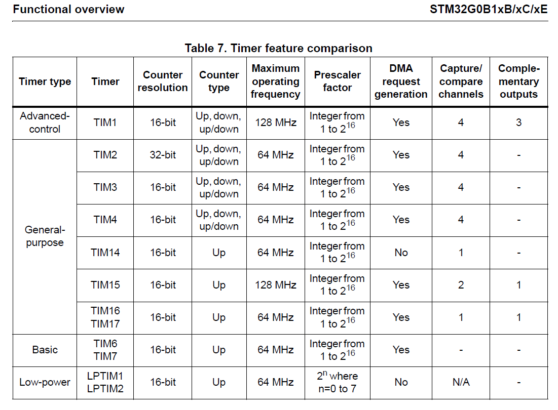
Note: Not all timers are available on every STM32G0 variant. The STM32G031B1 includes all 12 listed above.
🔧Key Timer Features
-
Prescaler (PSC): Divides the system clock to set the timer tick frequency. REG example:
TIM16->PSC -
Auto-Reload Register (ARR): Sets the period before the timer overflows or resets. REG example:
TIM16->ARR -
Capture/Compare Registers (CCR): Used for output compare, PWM, and input capture. REG example:
TIM16->CCR1 -
Interrupts: Timers can trigger interrupts on overflow or compare match. REG example:
TIM16->DIER -
PWM Modes: Edge-aligned and center-aligned PWM generation. REG example:
TIM16->CCMR1 -
One-Pulse Mode: Generate a single pulse after a trigger. REG example:
-
Complementary Outputs (TIM1 only): Useful for motor control and power electronics.
3️⃣ Events that can be generated with a timer
-
Update Event
UEVwhen the counter overflows/underflows (other events can generate this, R.M 22.4.1) -
Output compare event when the counter
TIM_x->CNTequals theTIM_x->CCRxregister -
Input capture event when an edge is detected in a
TIM_x->CCRxregister
The similar timers are grouped together in the same chapter the reference manual. For isntance, TIM15/TIM6/Tim17 in Chapter 25
4️⃣ Steps to configure timer to use the Update Event (UEV)
-
Set Prescaler in
TIM_x->PSCregister () -
Set auto-reload in
TIM_x->ARRregister (mod counter value) -
Enable timer counter (start timer) in
TIM_x->CR1register
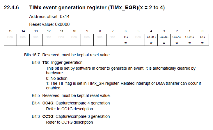
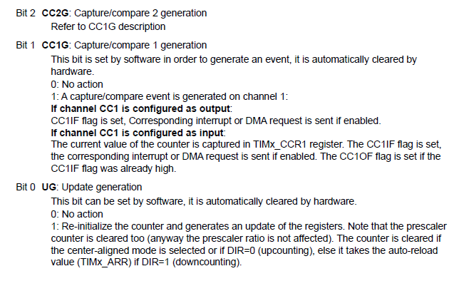
- Note Sometimes it is required to generate an update event to restart the counter or update registers in
TIM_x->EGR
5️⃣ Understanding Shadow Registers (Preloading)
-
In the STM32, many timer registers are buffered. This means there are actually two versions of the register:
-
The Preload Register: The one you (the programmer) can write to.
-
The Shadow Register: The one the hardware actually uses to count.
-
Why do we need this?
-
Imagine your timer is currently counting and has an ARR (limit) of 1000. The counter is currently at 800. If you suddenly change the ARR to 500, what happens?
-
Without a Shadow Register: The counter is now at 800, but the limit is 500. It will keep counting up until it hits 65535, wraps around to 0, and finally hits 500. Your timing is ruined for one full cycle!
-
With a Shadow Register: Your new value (500) sits in the “Preload” register. The hardware keeps counting to 1000 using the old value. The moment it hits 1000 (the Update Event), it “copies” your 500 into the Shadow register. The transition is seamless.
-
The “Update Event” (UEV)
- The transfer from Preload to Shadow only happens during an Update Event. This occurs naturally when the timer overflows (reaches its limit), or you can force it manually in code.
The Implementation Trap
- In your Timer_Init() function, you set the
PSCandARR. However, if you don’t force an update, the timer will use its default values (usually 0) until the first “natural” overflow occurs.
To fix this, we use the Event Generation Register (EGR):
timer->EGR |= TIM_EGR_UG; // Force an Update Event
- This ensures that the values you set in
PSCandARRare immediately loaded into the Shadow registers, and your timer starts with the correct timing from the get-go.
Timer Register Synchronization (Shadowing)
- In the STM32, the Prescaler (PSC) and Auto-Reload (ARR) registers are not directly connected to the counting hardware. Instead, they use a “Preload” and “Shadow” architecture to prevent timing glitches.
graph TD
    subgraph "Software Domain (User Accessible)"
        A[PSC Preload Register]
        B[ARR Preload Register]
    end

    subgraph "Hardware Domain (Internal Logic)"
        C[PSC Shadow Register]
        D[ARR Shadow Register]
        E[Counter - CNT]
    end

    A -- "Update Event (UEV)" --> C
    B -- "Update Event (UEV)" --> D

    C --> E
    D --> E
    E -- "Overflow / Manual UG bit" --> F((Update Event))
    F -.->|Triggers Copy| A
    F -.->|Triggers Copy| B
How to Explain the Data Flow:
-
The Preload Register: When the student writes timer->PSC = 40-1;, they are writing to the Preload register. The timer doesn’t care yet; it keeps counting using whatever value was already in the Shadow register.
-
The Update Event (UEV): This is the “Transfer Trigger.” It happens automatically when the counter reaches the ARR value (overflow), or manually when the student sets the UG bit in the EGR register.
-
The Shadow Register: This is the “Active” register. The hardware logic only looks at this register to determine the clock division and the reset point.