📚 Assignment 8 CMPE1250: Timers Output Compare and PWM
📋 Overview
-
In this ICA you will explore two common applications of pulse width modulation.
-
You will need a breadboard and some of the components from your parts kit for this exercise. If required your instructor may have some parts to share.
1️⃣ Part A - LED Brightness Control
-
Map PA5 (
LD2) to alternate an alternate function so it can re driven by a timer. -
Configure the timer in PWM mode, 1kHz frequency. Cycle the duty in the range of 5% duty to 95% duty over a 1s interval. You may implement the cycling as sawtooth, ramp up/down, or sinusoidal. Observe this waveform on a scope.
-
Challenge - write a program that will alter the PWM duty periodically and somewhat randomly to have the LED appear to flicker like a candle.
2️⃣ Part B - Budget DAC
- Build now the following circuit on PA7:
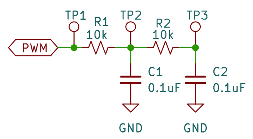
-
Configure TIM14 for PWM mode with a 2kHz frequency. Use the largest value you can for ARR to ensure you have the highest control over the duty. Set the duty initially to 50%. Ensure you measure a 2kHz 50% duty waveform on PA7 at test point 1.
-
Sketch the waveform at TP1, TP2, and TP3. How does this match your expectations for the given circuit?
| TP1 | TP2 | TP3 |
|---|---|---|
-
Connect the SW1 and SW4 of the button board to PC10 and PC12 Respectively. Configure the buttons to increase and decrease the duty cycle by 5% each time they are pressed. The minimum duty should be 0% and the maximum duty should be 100%. Observe the changes on the scope at TP1, TP2, and TP3 as you press the buttons. Sw1 should decrease the duty and SW4 should increase the duty.
-
Measure the output voltage using a DMM at TP3 for the following duty values:
| PWM Duty (as %) | Voltage measured at the test point |
|---|---|
| 0 | |
| 5 | |
| 25 | |
| 50 | |
| 75 | |
| 100 |
- How do the voltages measured at their respective duties relate to the circuit supply of 3.3V?