📚 CMPE1250: Introduction to Timers
🎯 Learning Objectives
By the end of this lesson, students will be able to:
- Understand how STM32 timers generate periodic events.
- Configure prescaler and ARR to control tick timing.
- Enable overflow interrupts for periodic tasks.
- Use output compare and PWM modes to generate signals.
1️⃣ Introduction
Timers are hardware peripherals that count in ticks (as a mutiple of the clock cycles) to measure time intervals, generate periodic events, or produce waveforms. They are essential for:
- Delays and timeouts
- Interrupt-driven scheduling
- PWM signal generation
- Input signal measurement (e.g., frequency, pulse width)
2️⃣ STM32G031K8 Timer Overview
The STM32G031K8 features a mix of basic, general-purpose, and advanced-control timers. These peripherals are essential for time-based operations such as delays, periodic interrupts, PWM generation, and signal measurement.
🔧Timer Types and Capabilities (DS 3.16)
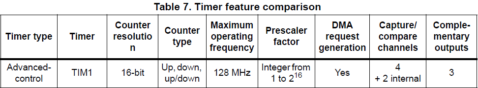
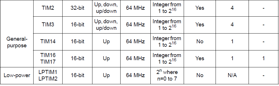
Note: Not all timers are available on every STM32G0 variant. The STM32G031K8 includes all six listed above.
🔧Key Timer Features
-
Prescaler (PSC): Divides the system clock to set the timer tick frequency. REG example:
TIM16->PSC -
Auto-Reload Register (ARR): Sets the period before the timer overflows or resets. REG example:
TIM16->ARR -
Capture/Compare Registers (CCR): Used for output compare, PWM, and input capture. REG example:
TIM16->CCR1 -
Interrupts: Timers can trigger interrupts on overflow or compare match. REG example:
TIM16->DIER -
PWM Modes: Edge-aligned and center-aligned PWM generation. REG example:
TIM16->CCMR1 -
One-Pulse Mode: Generate a single pulse after a trigger. REG example:
-
Complementary Outputs (TIM1 only): Useful for motor control and power electronics.
3️⃣ Events that can be generated with a timer
-
Update Event
UEVwhen the counter overflows/underflows (other events can generate this, R.M 22.4.1) -
Output compare event when the counter
TIM_x->CNTequals theTIM_x->CCRxregister -
Input capture event when an edge is detected in a
TIM_x->CCRxregister
The similar timers are grouped together in the same chapter the reference manual. For isntance, TIM15/TIM6/Tim17 in Chapter 25
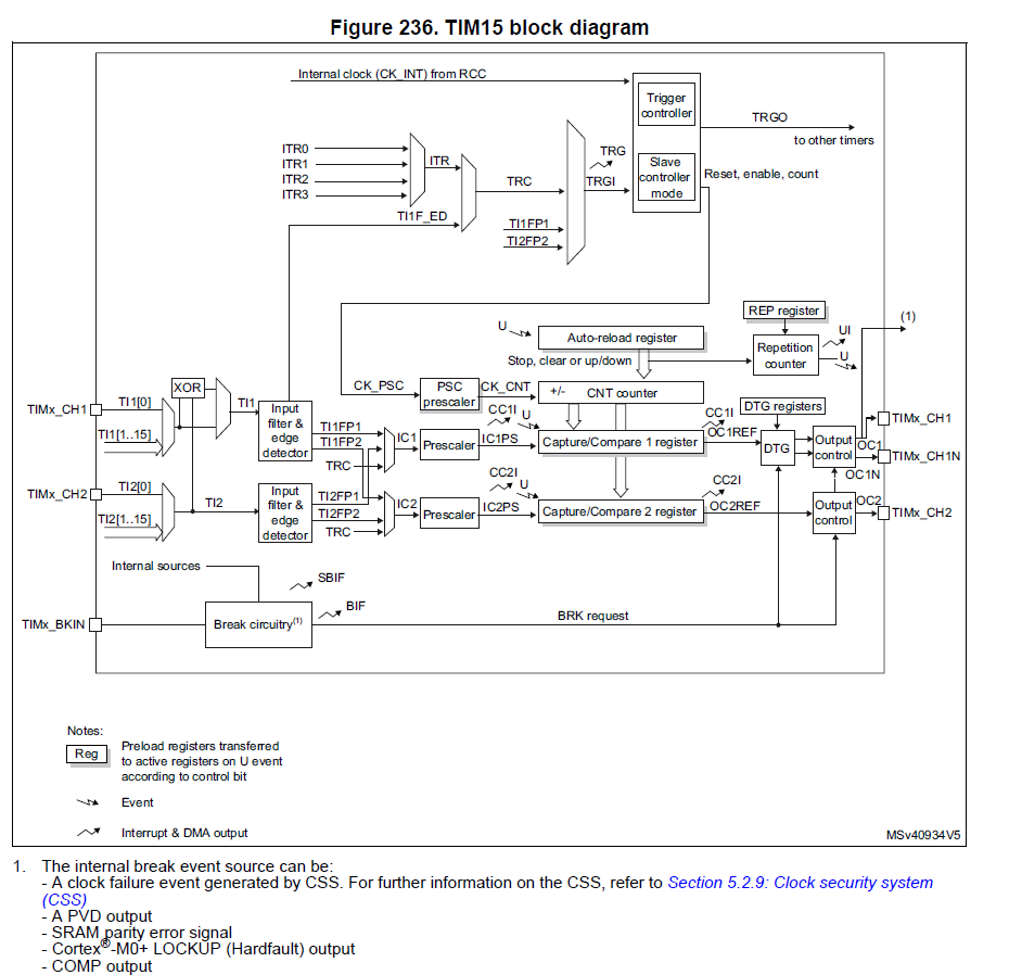
RM 25.2
4️⃣ Steps to configure timer
-
Set Prescaler in
TIM_x->PSCregister -
Set auto-reload in
TIM_x->ARRregister -
Configure Capture/compare register if required in
TIM_x->CCRxregister -
Enable interrrupt if required in
TIM_x->DIERregister -
Configure toggle mode or PWM mode if in output compare in
TIM_x->CCMR1or `TIM_x->CCMR2 -
Enable Capture/compare channel, if required in
TIM_x->CCERregister -
Enable timer counter (start counter) in
TIM_x->CR1register
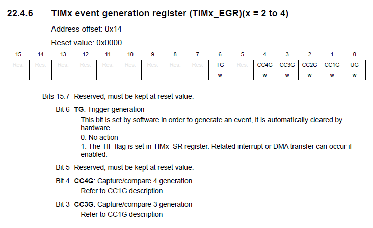
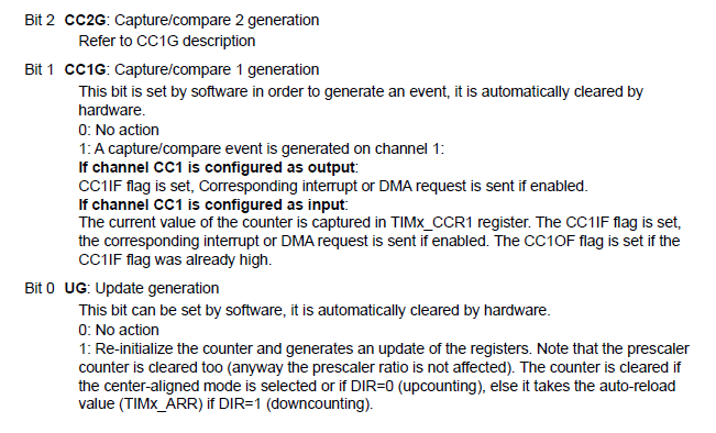
- Note Sometimes it is required to generate an update event to restart the counter or update registers in
TIM_x->EGR