📚 CMPE1250: Clock System Extension: Performance Considerations
🎯 Learning Objectives
By the end of this lesson, students will be able to:
- Identify considerations to make when running the micro at speeds higher than 24MHz
- Describe instruction prefetching and its impact on execution efficiency.
- Configure GPIO speed settings based on application requirements and understand their trade-offs
- Apply performance tuning techniques to optimize embedded system responsiveness and reliability.
1️⃣ Flash Latency
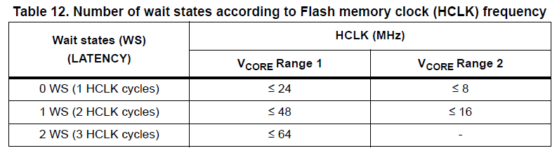
When the system clock exceeds 24 MHz, the Flash memory access time becomes critical. The CPU may attempt to fetch instructions faster than the Flash can deliver them, leading to wait states unless latency is adjusted.
-
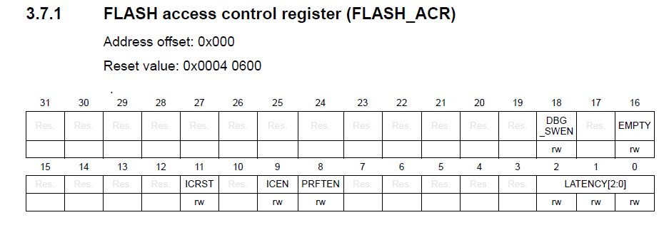
Flash latency (RM 3.3.4) is configured via the
FLASH_ACRregister (RM 3.7.1). -
For STM32G0 series, latency settings typically range from 0 to several wait states depending on voltage and clock speed.
-
Rule of thumb:
- 0 wait states for ≤ 24 MHz
- 1 wait state for 24–48 MHz
- 2+ wait states for higher speeds
- Example configuration
FLASH->ACR |= FLASH_ACR_LATENCY_0; // Set 1 wait state
FLASH->ACR |= FLASH_ACR_LATENCY_1; // Set 2 wait states
2️⃣ Instruction Prefetch and Cache
To mitigate latency and improve performance, STM32 devices offer instruction prefetch and sometimes cache mechanisms.
-
Prefetch buffer allows the CPU to fetch instructions ahead of time, reducing stalls.
-
Enabled via
FLASH_ACR: -
Best practice: Always enable prefetch when running above 24 MHz, especially if Flash latency is increased.

- Example configuration
FLASH->ACR |= FLASH_ACR_PRFTEN; // Enable prefetch
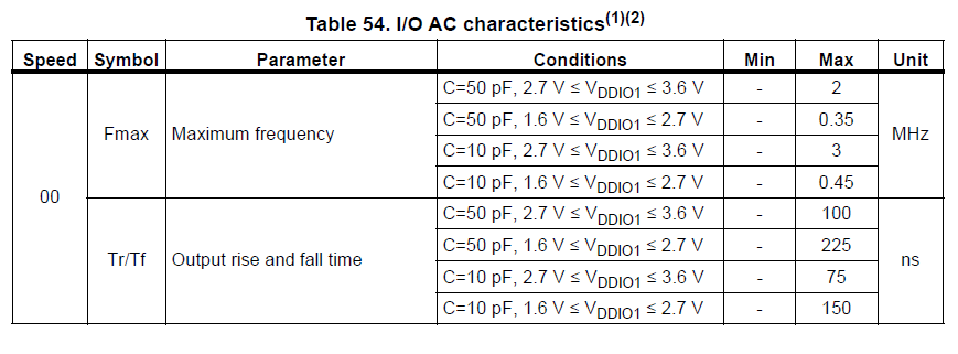
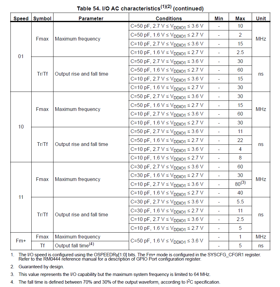
3️⃣ GPIO Speed Settings and Clock Impact
GPIO speed settings affect how fast pins can toggle, which is crucial for high-frequency signaling (e.g., SPI, PWM).
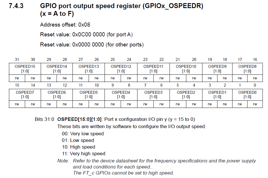
- Configured via
GPIOx_OSPEEDRregister (RM 7.4.3).
-
Speed options (
DS Table 54):- (00) Low speed: ~2 MHz
- (01) Medium speed: ~10 MHz
- (10) High speed: ~50 MHz
- (11) Very high speed (on some devices): ~100 MHz
-
Estimate max frequency according to speed settings:
\[f_{\mathrm{max}}\approx \frac{1}{2\cdot t_{\mathrm{rise}}}\]
- Example:
GPIOA->OSPEEDR |= (0x2 << (2 * PIN)); // Set high speed for PIN
📚 Summary
- Flash latency must be adjusted when SYSCLK > 24 MHz to avoid CPU stalls.
- Instruction prefetch improves performance and should be enabled with higher clock speeds.
- GPIO speed settings allow fine control over pin performance—balance speed with power and EMI.