🧠 Getting Started with STM32G031xx.h — Masks & Structs
🎯 Learning Objectives
By the end of this lesson, students will:
- Understand the purpose of the STM32G031xx.h header file
- Learn how peripheral registers are accessed using data structures
- Use bit masks to manipulate register values
- Write simple code to control GPIO using register-level programming
Part1: 📘 What Is STM32G031xx.h?
This header file is part of the CMSIS (Cortex Microcontroller Software Interface Standard) and provides:
- Definitions for peripheral base addresses
- Bit masks for register fields
- Memory-mapped structs for hardware registers
Example snippet from the file:
#define GPIOA_BASE (0x50000000UL)
#define GPIOA ((GPIO_TypeDef *) GPIOA_BASE)
🧱 Part 2: Understanding Data Structures and Registers
Peripheral registers are grouped into structs. For example, GPIO_TypeDef might look like:
typedef struct {
  volatile uint32_t MODER;   // GPIO port mode register
  volatile uint32_t OTYPER;  // GPIO port output type register
  volatile uint32_t OSPEEDR; // GPIO port output speed register
  volatile uint32_t PUPDR;   // GPIO port pull-up/pull-down register
  volatile uint32_t IDR;     // GPIO port input data register
  volatile uint32_t ODR;     // GPIO port output data register
} GPIO_TypeDef;
Let’s say we want to modify the MODER register for GPIOA
- Each port, in this case GPIOA, has 16-PINs (GPIA15..GPIOA00)
- To configure the MODER register, we need 2-bits per Port PIN as there are 4 possible configurations:
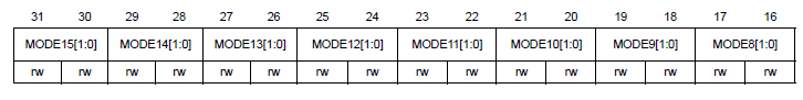
- Then the MODER register has 16x2 = 32bits (b31..b00) to configure it according to the following table:
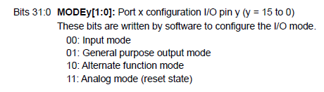
- The 32-bits of the MODER register as distributed as follows:
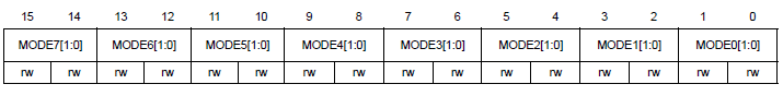
- Let’s say we want to configure GPIOA0 as an output, that means we need to write 10b on b1 and b0 of the MODER register.
GPIOA->MODER = 0x00000001; // Set PA0 as output
- 0x00000001 = 00000000 000000000 000000000 000000001 in binary
- If we wanted to configure GPIOA10 as an output, that means we need to write 10b on b21 and b00 of the MODER register.
GPIOA->MODER = 0x00200000; // Set PA0 as output
- 0x00000001 = 00000000 000100000 000000000 000000000 in binary
🎭 Part 3: Using Bit Masks
- The vendor provide us with convinient masks to avoid having to write raw numbers in hex or binary
- Extract from the header file (STM32G031xx.h)
#define GPIO_MODER_MODE0_Msk (0x3U << 0)  // Mask for PA0 mode bits
#define GPIO_MODER_MODE0_Output (0x1U << 0)

GPIOA->MODER &= ~GPIO_MODER_MODE0_Msk;       // Clear PA0 mode bits
GPIOA->MODER |= GPIO_MODER_MODE0_Output;     // Set PA0 as output
🎯 Part 4: Sumary - Write Into the Registers using Masks
- Clear the BITS using the *xxx_Msk
- Write the proper BITS using the corresponding mask for the BITS
🧩 Part 5: Challenge for Students
- Configure GPIOA12 as output using the BIT masks from the library
- Configure GPIOA15 as analog mode using the BIT masks from the library
- Verify it is working by using the debugger