📚 LAB 3 CMPE2250: Building the SPI LCD Library
📋 Overview and Introduction
- In this lab, you will develop a driver for a 160x128 TFT LCD using the ST7735 controller. You will learn how to bridge low-level SPI communication with high-level graphics functions.
Hardware Configuration
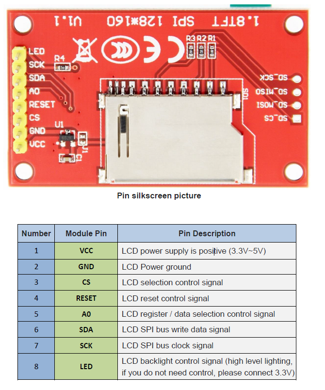
- The LCD module hardware circuit comprises two parts: an LCD display control circuit and a backlight control circuit.
- The LCD display control circuit is used to control the pins of the LCD, including control pins and data transfer pins.
- The backlight control circuit is used to control the backlight to be on and off. Of course, if the backlight is not required to be controlled, the backlight control pin can be directly connected to the 3.3V power supply without using the circuit.
Working Principle
- Introduction to ST7735S Controller
-
The ST7735S controller supports a maximum resolution of 132*162 and a 48114-byte GRAM. It also supports 8-bit, 9-bit, 16-bit, and 18-bit parallel port data buses. It also supports 3-wire and 4-wire SPI serial ports.
-
Since parallel control requires a large number of IO ports, the most common one is SPI serial port control. The ST7735S also supports 65K, 262K RGB color display, display color is very rich, while supporting rotating display and scroll display and video playback, display in a variety of ways.
-
The ST7735S controller uses 16bit (RGB565) to control a pixel display, so it can display up to 65K colors per pixel. The pixel address setting is performed in the order of rows and columns, and the incrementing and decreasing direction is determined by the scanning mode. The ST7735S display method is performed by setting the address and then setting the color value.
- Introduction to SPI communication protocol
- The 4-wire SPI bus write mode timing is shown in the following figure:
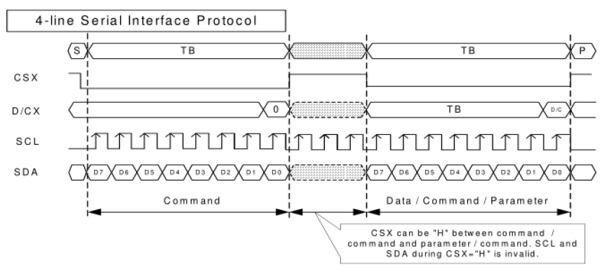
- CSX is a slave chip select, and the chip is enabled only when CSX is low.
- D/CX is the data/command control pin of the chip. When DCX is low, the command is written.When it is high, the data is written.
- SCL is the SPI bus clock, and each rising edge transmits 1 bit of data.
- SDA is the data transmitted by SPI, and it transmits 8-bit data at a time. The data format is as shown below:
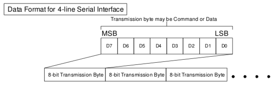
- The high position is in front and transmitted first (MSB first).
- For SPI communication, the data has a transmission timing, that is, a combination of clock phase (CPHA) and clock polarity (CPOL):
- The CPOL level determines the idle state level of the serial synchronous clock, CPOL = 0, which is low. CPOL does not have a lot of impact on the transport protocol.
- The level of CPHA determines whether the serial synchronous clock is acquired on the first clock transition edge or the second clock transition edge.
- When CPHL = 0, data acquisition is performed on the first edge of the transition;
- The combination of the two becomes the four SPI communication methods. SPI0 is usually used in China, that is, CPHL = 0, CPOL = 0.
1️⃣ Preparatory Work
- We suggest using this pin connections to be able to test the binary provided by the instructor
| NUMBER | PIN | DESC | NUCLEO PIN | AF |
|---|---|---|---|---|
| 1 | VCC | 3.3V | * | N/A |
| 2 | GND | Ground | * | N/A |
| 3 | CS | GPIO (active LOW) | PD5 | N/A |
| 4 | RESET | GPIO (active LOW) | PC8 | N/A |
| 5 | A0 | GPIO, CMD = 0 / DATA = 1 | PC6 | N/A |
| 6 | SDA | SPI MOSI | PA12 | 0 |
| 7 | SCK | SPI Clock | PB3 | 0 |
| 8 | LED | PWM backlight, any PWM Pin or 3.3V | Any | * |
2️⃣ Header and Data Structures
-
The provided data struct defines the Driver Struct:
- Addresses of the SPI peripheral
- Timer for delays
- GPIO ports/pins for:
- CS (Chip Select)
- RST (Reset)
- DC (Data/Command).
    typedef struct LCD_Driver__
    {
        TIM_TypeDef* timer;
        SPI_TypeDef* spi;
        GPIO_TypeDef* csPort;
        uint16_t csPin;
        GPIO_TypeDef* rstPort;
        uint16_t rstPin;
        GPIO_TypeDef* dcPort;
        uint16_t dcPin;
    } LCD_Driver_t;
- All the GPIO pins must be initialized as Ouput
- Define Constants: Set your screen width (160) and height (128).
    #define ST7735_WIDTH  160
    #define ST7735_HEIGHT 128
- Ultimately the width and height will depend on the orientation (portrait or landscape)
- Rotation Enums: Define an enumeration for screen rotation to make your code readable.
    typedef enum LCD_Rotation__
    {
        LCD_ROT_0_P1 = 0x00,
        LCD_ROT_0_P2 = 0xC0,
        LCD_ROT_90_CW = 0x60,
        LCD_ROT_180 = 0xC0,
        LCD_ROT_270_CW = 0xA0
    }LCD_Rotation_t;
3️⃣ Low-Level Communication (The “Private” Functions)
-
The ST7735 distinguishes between a Command and Data using the DC pin.
-
Command Mode:
Pull DC LOW,pull CS LOW, send the byte via SPI, thenpull CS HIGH. -
Data Mode:
Pull DC HIGH,pull CS LOW, send the byte(s) via SPI, thenpull CS HIGH. -
Buffer Support: Implement “Buf” versions of these functions to send arrays of data (essential for filling the screen quickly).
    void LCD_ST7735_Cmd(LCD_Driver_t* lcd, uint8_t c);
    void LCD_ST7735_CmdBuf(LCD_Driver_t* lcd, uint8_t *cmdBuf, uint8_t *rxDataBuf, uint32_t len);
    void LCD_ST7735_Data(LCD_Driver_t* lcd, uint8_t d);
    void LCD_ST7735_DataBuf(LCD_Driver_t* lcd, uint8_t *txDataBuf, uint8_t *rxDataBuf, uint32_t len);
- Since these functions are private helpers, they should be declares as prototypes on the top inside st7735.c, not accesible from st7735.h
4️⃣ Hardware Initialization (low level) and Reset
Before sending commands, the hardware needs to be physically ready.
- HAL Init: Write a function to assign the GPIO and SPI handles to your driver struct and initialize those pins as outputs.
    void LCD_ST7735_HAL_Init(LCD_Driver_t* lcd, SPI_TypeDef* spi,
                            GPIO_TypeDef* cs_Port, uint16_t cs_Pin,
                            GPIO_TypeDef* rst_Port, uint16_t rst_Pin,
                            GPIO_TypeDef* dc_Port, uint16_t dc_Pin)
    {
        // 1. Assign the passed SPI and GPIO parameters to the 'lcd' struct members.
        // 2. Initialize the CS, RST, and DC pins as Output pins using your GPIO driver.
        // 3. Set CS High and RST High as their default 'idle' states.
    }
-
*Hardware Reset: To reset the ST7735, toggle the RST pin:
-
Pull RST LOW.
-
Wait ~10ms.
-
Pull RST HIGH.
-
    void LCD_ST7735_Reset(LCD_Driver_t* lcd)
    {
        // 1. Pull the RST pin LOW.
        // 2. Delay for 10ms (Use your Timer_Delay_ms function).
        // 3. Pull the RST pin HIGH.
    }
5️⃣ The “InitSequence”
-
Goal: Wake the hardware up in the correct order.
-
Hardware Reset: Call your Reset function.
-
Delay: Wait
120ms(crucial for the controller to stabilize). -
Sleep Out: Send
Command 0x11. -
Delay: Wait another
120ms. -
Color Mode: Send
Command 0x3A, thenData 0x05(Sets 16-bit RGB565 mode). -
Rotation: Send Command
0x36, thenData rot. -
Display ON: Send
Command 0x29.
-
    void LCD_ST7735_InitSequence(LCD_Driver_t* lcd, LCD_Rotation_t rot, TIM_TypeDef* _timer)
    {
        // 1. Assign the timer to the lcd struct and initialize the ticker.
        // 2. Execute a Hardware Reset using LCD_ST7735_Reset().
        // 3. Delay 120ms.
        // 4. Send Command 0x11 (Sleep Out).
        // 5. Delay 120ms.
        // 6. Send Command 0x36 (Memory Data Access Control), then Data 'rot'.
        // 7. Send Command 0x3A (Interface Pixel Format), then Data 0x05 (16-bit color).
        // 8. Send Command 0x29 (Display ON).
    }
6️⃣ The Private Helpers: Cmd vs Data
-
Goal: Tell the ST7735 if the incoming byte is an instruction (Cmd) or a pixel(Data).
-
For Commands:
- Pull DC Low (0) — This tells the controller “Instruction incoming.”
- Pull CS Low (0) — Select the chip.
- Call SPI_TxRxByte() to send the command byte.
- Pull CS High (1) — Deselect the chip.
-
For Data:
- Pull DC High (1) — This tells the controller “Data/Parameters incoming.”
- Pull CS Low, send the byte via SPI, then pull CS High.
- Call SPI_TxRxByte() to send the data byte.
- Pull CS High (1) — Deselect the chip.
    void LCD_ST7735_Cmd(LCD_Driver_t* lcd, uint8_t c)
    {
        // 1. Set the Data/Command (DC) pin LOW to indicate a Command is being sent.
        // 2. Set Chip Select (CS) LOW to talk to the LCD.
        // 3. Use your SPI driver to transmit the single byte 'c'.
        // 4. Set Chip Select (CS) HIGH to finish the communication.
    }

    void LCD_ST7735_Data(LCD_Driver_t* lcd, uint8_t d)
    {
        // 1. Set the Data/Command (DC) pin HIGH to indicate Data is being sent.
        // 2. Set Chip Select (CS) LOW to talk to the LCD.
        // 3. Use your SPI driver to transmit the single byte 'd'.
        // 4. Set Chip Select (CS) HIGH to finish the communication.
    }
Bulk Transfers (CmdBuf and DataBuf)
-
Use Case: Streaming pixel data to the screen (like in FillScreen or drawing large shapes). By asserting CS Low just once, you can blast an entire array of memory out of the SPI hardware, drastically improving your frame rate.
-
Logic for CmdBuf (Command Buffer):
-
Pull DC Low (0).
-
Pull CS Low (0).
-
Pass the array pointer (cmdBuf) and the total number of bytes (len) to your block-transmit SPI function (e.g., SPI_TransmitReceive()). Let the hardware handle the loop!
-
Wait for the SPI peripheral to finish, then pull CS High (1).
-
    void LCD_ST7735_CmdBuf(LCD_Driver_t* lcd, uint8_t *cmdBuf, uint8_t *rxDataBuf, uint32_t len)
    {
        // 1. Set the Data/Command (DC) pin LOW to indicate a Command is being sent.
        // 2. Set Chip Select (CS) LOW to talk to the LCD.
        // 3. Use your SPI driver's "TransmitReceive" function to send the 'txDataBuf'  of length 'len'.
        // 4. Set Chip Select (CS) HIGH to finish the communication.
    }
-
Logic for DataBuf (Data Buffer):
-
Pull DC High (1).
-
Pull CS Low (0).
-
Pass the array pointer (txDataBuf) and the length (len) to your block-transmit SPI function.
-
Wait for the transmission to complete, then pull CS High (1).
-
    void LCD_ST7735_Data(LCD_Driver_t* lcd, uint8_t d)
    {
        // 1. Set the Data/Command (DC) pin HIGH.
        // 2. Set Chip Select (CS) LOW.
        // 3. Use your SPI driver's "TransmitReceive" function to send the 'txDataBuf'  of length 'len'.
        // 4. Set Chip Select (CS) HIGH.
    }
7️⃣ SetAddressWindow(x0, y0, x1, y1)
-
Goal: Define the “Drawing Box.”
-
Step 1: Send Command
0x2A(Column Address Set). -
Step 2: Send 4 Data bytes:
0x00, x0, 0x00, x1. (The 0x00 is because the ST7735 expects 16-bit coordinates, but our screen is only 160 pixels wide). -
Step 3: Send Command
0x2B(Row Address Set). -
Step 4: Send 4 Data bytes:
0x00, y0, 0x00, y1. -
Step 5: Send Command
0x2C(Memory Write). This “opens the gate” for pixel data to flow into the box you just defined.
    void LCD_ST7735_SetAddressWindow(LCD_Driver_t* lcd, uint8_t x0, uint8_t y0, uint8_t x1, uint8_t y1)
    {
        // 1. Send Command 0x2A (Column Address Set).
        // 2. Send 4 Data bytes: 0x00, x0, 0x00, x1.
        // 3. Send Command 0x2B (Row Address Set).
        // 4. Send 4 Data bytes: 0x00, y0, 0x00, y1.
        // 5. Send Command 0x2C (Memory Write) to prepare the LCD for pixel streaming.
    }
8️⃣ FillScreen(color)
-
Goal: Color every single pixel.
-
Step 1: Call
SetAddressWindow(0, 0, WIDTH-1, HEIGHT-1). - Step 2: Prepare a 2-byte buffer.
- buf[0] = color » 8 (High Byte)
- buf[1] = color & 0xFF (Low Byte)
-
Step 3: Create a loop that runs $160 \times 128$ times ($20,480$ iterations).
- Step 4: Inside the loop, send that 2-byte buffer using your
DataBuffunction.
    void LCD_ST7735_FillScreen(LCD_Driver_t* lcd, uint16_t color)
    {
        // 1. Set the address window to the full size of the screen (0, 0, WIDTH-1, HEIGHT-1).
        // 2. Prepare an 8-bit buffer with the 16-bit color (High byte first, then Low byte).
        // 3. Loop through every pixel (Total = WIDTH * HEIGHT).
        // 4. In each iteration, call LCD_ST7735_DataBuf to send your 2-byte color buffer.
    }
8️⃣ 5. DrawChar(x, y, char, color, bg)
-
Goal: Translate a bitmask (font) into pixels.
-
Step 1: Locate the character in your font array (usually char - 32 for ASCII).
-
Step 2: Outer Loop: Iterate through the 5 columns of the font.
-
Step 3: Inner Loop: Iterate through the 8 bits (rows) of that column’s byte.
-
Step 4: Check the bit:If the bit is
- 1: Call DrawPixel at current $(x, y)$ using color.
- If the bit is 0: Call DrawPixel at current $(x, y)$ using bg (background).
-
Step 5: Shift your bitmask and increment your coordinates.
-
Understanding the 5x7 Font
-
To draw a character, we don’t send an “A” to the screen; we send a grid of colored pixels. We store these grids in a font array.
-
Our library uses a 5x7 Font. This means each character is 5 pixels wide and 7 pixels tall. However, to make memory alignment easier, we pad the height to 8 pixels (1 byte).
-
Therefore, every character is made up of 5 bytes (one byte per vertical column).
-
Example: The Letter
A
Imagine the 5 bytes that make up the letter ‘A’. The bits in each byte represent the pixels in that column from top (Bit 0) to bottom (Bit 7).
     Col 0  Col 1  Col 2  Col 3  Col 4
Bit 0:   0      1      1      1      0    (Top of 'A')
Bit 1:   1      0      0      0      1
Bit 2:   1      0      0      0      1
Bit 3:   1      1      1      1      1    (Middle bar of 'A')
Bit 4:   1      0      0      0      1
Bit 5:   1      0      0      0      1
Bit 6:   1      0      0      0      1    (Bottom of 'A')
Bit 7:   0      0      0      0      0    (Blank space below)
How the Nested Loop Works:
-
The Outer Loop (Columns): Grabs one byte at a time (e.g., Col 0).
-
The Inner Loop (Rows): Looks at the 8 individual bits of that byte.
-
The Bit Mask: We use the bitwise AND operator (& 0x01) to check if the very first bit is a 1 or a 0.
-
If it’s 1, we draw a pixel using the text color.
-
If it’s 0, we draw a pixel using the background color.
-
The Shift: After checking the bit, we shift the byte to the right (»= 1) so the next bit moves into the first position for the next inner loop iteration.
// 1. BOUNDARY CHECK:
    // The font array only contains characters from ASCII 32 (' ') to ASCII 127 ('~').
    // If 'c' is outside this range, change 'c' to a default character (e.g., '?').

    // 2. GET THE FONT DATA:
    // Create a pointer to the specific character's 5-byte array.
    // Example: const uint8_t *bitmap = font5x7[c - 32];
    // (We subtract 32 because ASCII 32 is at index 0 in our array).

    // 3. OUTER LOOP: Iterate through the 5 columns (Width)
    // Create a 'for' loop using a variable 'col' from 0 to 4.
    // {
        // a. Grab the current column's byte from the bitmap:
        //    uint8_t line = bitmap[col];

        // b. INNER LOOP: Iterate through the 8 bits of this column (Height)
        //    Create a 'for' loop using a variable 'row' from 0 to 7.
        //    {
            // i. Check if the lowest bit is a 1:  if (line & 0x01)
            //    - If TRUE: Call LCD_ST7735_DrawPixel at (x + col, y + row) with 'color'.
            //    - If FALSE: Call LCD_ST7735_DrawPixel at (x + col, y + row) with 'bg'.

            // ii. Shift the 'line' variable right by 1 bit (line >>= 1)
            //     so the next bit is ready for the next iteration of the inner loop.
        //    }
    // }

    // 4. CHARACTER SPACING:
    // After the outer loop finishes, the character is drawn!
    // But we need a 1-pixel gap between this character and the next one.
    // Create one final loop from row = 0 to 7, and draw a vertical line of pixels
    // at x-coordinate (x + 5) using the background color 'bg'.