📚 CMPE2250: Inter-Integrated Circuit (I2C) on STM32G0
🎯 Overview
The Inter-Integrated Circuit (I2C) protocol is a synchronous, multi-master, multi-slave communication bus that strikes a unique balance between pin efficiency and system scalability. To understand its value, it helps to compare it to other common serial protocols. Unlike UART, which is asynchronous and strictly point-to-point, I2C uses a shared clock line to perfectly synchronize data transfers across many devices. Furthermore, while SPI offers incredibly fast full-duplex communication, it requires a dedicated physical Chip Select (CS) wire for every single slave added to the system, causing routing complexity to scale up quickly. I2C solves this hardware footprint issue by using a strictly two-wire interface—Serial Data (SDA) and Serial Clock (SCL). Instead of physical selection wires, I2C relies on a built-in software addressing scheme, allowing a microcontroller to seamlessly communicate with dozens of sensors, memories, and displays over the exact same two pins.
1️⃣ I2C Protocol Fundamentals
-
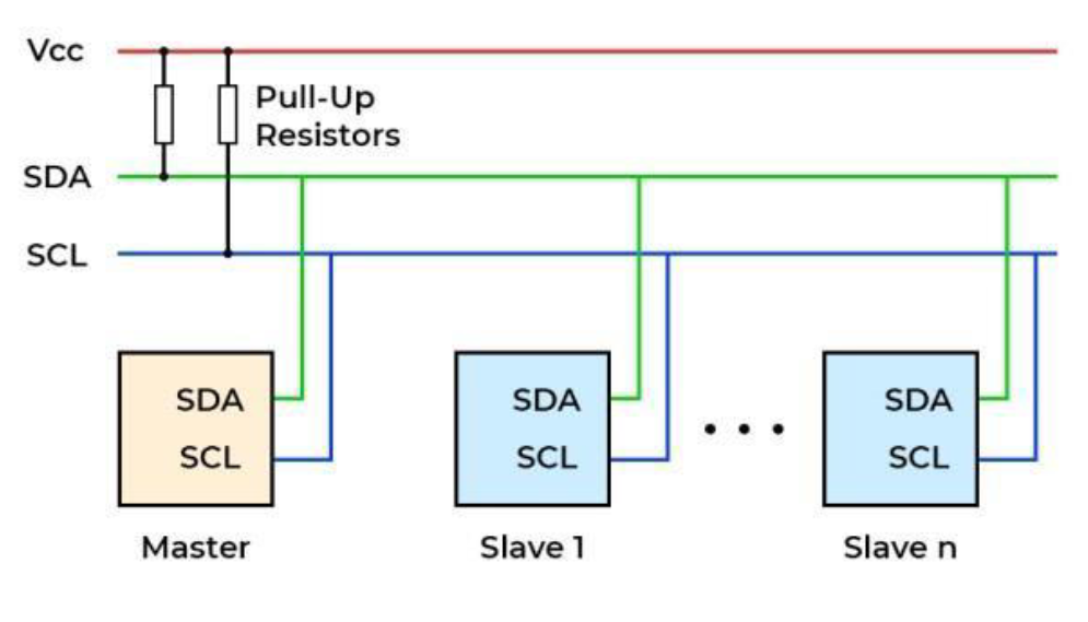
Hardware Requirements: I2C uses a two-wire interface consisting of
SDA(Data) andSCL(Clock) lines. Both lines require Pull-Up Resistors connecting them to Vcc. -
Communication Flow: A standard communication sequence is composed of four parts: a
STARTsignal, a slaveADDRESStransmission, aDATAtransfer, and aSTOPsignal. -
Data Validity: The data on the SDA line is only valid when the
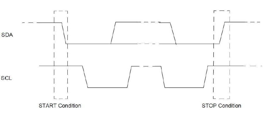
SCL line is HIGH. -
START Condition: The Master initiates communication by driving the SDA line LOW while the SCL line is HIGH.
-
STOP Condition: The Master releases the bus by driving the SDA line HIGH while the SCL line is HIGH.
-
Repeated START: A new START condition can be generated without having sent a STOP. This is typically used to change the data direction (e.g., switching from writing to reading) without releasing the bus.
 .
.
 .
.
2️⃣ Addressing and Data Transfer
-
Slave Addressing: I2C supports 7-bit and 10-bit addressing.
-
The R/W Bit: For standard 7-bit addressing, the address is transmitted with a READ/WRITE operation bit appended as the Least Significant Bit. A 1 indicates a READ operation, and a 0 indicates a WRITE operation.
-
ACK/NACK: After a byte is transmitted, the receiving device must acknowledge it. The slave device brings the SDA line LOW to indicate an Acknowledge (ACK), or leaves it HIGH for a Not Acknowledge (NACK).
3️⃣ Reading and Writing Device Registers
Many I2C sensors require pointing to a specific internal register before reading or writing data.
Writing to a Register:
-
Master provides a START condition.
-
Master provides the Slave Address and sets the R/W bit to WRITE (0).
-
Master writes the Register Byte.
-
Master writes the Data Byte.
-
Master provides a STOP condition.
Reading from a Register:
-
Master provides a START condition.
-
Master provides the Slave Address and sets the R/W bit to WRITE (0).
-
Master writes the Register Byte to set the internal pointer.
-
Master provides a Repeated START condition.
-
Master sends the Slave Address again, but with the R/W bit set to READ (1).
-
Master reads the Data Byte.
-
Master provides a NACK if it is only reading one byte.
-
Master provides a STOP condition.
4️⃣ STM32G0 Specific I2C Features
The STM32G0 incorporates a highly flexible I2C peripheral that manages much of the protocol sequencing and timing in hardware.
Performance & Speeds:
-
The peripheral supports Standard, Fast, and Fast-mode Plus (up to 1 MHz).
-
Standard-mode (Sm): Operates at speeds up to 100 kbit/s. This is the baseline speed and is sufficient for basic sensor configurations, simple EEPROM reads, and low-frequency data polling.
-
Fast-mode (Fm): Operates at speeds up to 400 kbit/s. This is the most common operating speed for modern I2C sensors and displays, offering a good balance between speed and reliability over moderate wire lengths.
-
Fast-mode Plus (Fm+): Operates at speeds up to 1 Mbit/s (1000 kbit/s). To achieve the sharp signal edges required at this frequency, the bus requires stronger pull-up currents. On modern microcontrollers like the STM32G0, utilizing Fm+ often requires routing the signal to specific I/O pins that support a higher 20 mA output drive.
-
-
For Fast-mode Plus, the IO pins support the required 20 mA output drive.
-
It includes hardware support for SMBus 3.0 and PMBus 1.3 compatibility.
Hardware Timing and Integrity:
-
Independent Clock: The peripheral has an independent clock domain, allowing the I2C baud rate to remain completely independent from the main system clock.
-
Programmable Timings: Setup and Hold times are fully programmable by software.
-
Noise Filters: Programmable analog and digital glitch filters are available on both the SCL and SDA lines.
-
Clock Stretching: Supported from both the master and slave sides.
Clock Stretching
- The Concept
- In an I2C bus, the Master device is strictly responsible for generating the SCL (clock) signal that drives the communication. However, there are times when a Slave device needs more time to process information. For example, the Slave might need extra time to write a received byte into its internal EEPROM, or it might be busy completing an Analog-to-Digital conversion before it can send the requested data back to the Master. Clock stretching is the mechanism the Slave uses to tell the Master to “pause.”
- How It Works at the Hardware Level
-
Because both the SDA and SCL lines are “open-drain” (meaning devices can only pull the line LOW to ground, while a resistor pulls it HIGH to Vcc), any device on the bus can hold a line LOW.
-
During normal data transfer, the Master pulses the SCL line HIGH and LOW.
-
If the Slave needs to pause communication, it waits for the Master to drive the SCL line LOW during the clock cycle.
-
The Slave then actively asserts its own LOW signal on the SCL line.
-
When the Master attempts to transition to the next phase by releasing the SCL line (expecting the pull-up resistor to pull it HIGH), the line remains LOW because the Slave is still holding it down.
-
The Master’s Wait State: The protocol requires the Master to monitor the actual state of the SCL line. When it sees that SCL is still LOW despite having released it, the Master recognizes that clock stretching is occurring. The Master will halt its internal clock generation and wait.
-
Once the Slave has finished its internal processing, it releases the SCL line. The pull-up resistor finally pulls the SCL line HIGH, and the Master resumes clocking the bus from where it left off.
-
-
Advanced Slave Addressing:
-
The STM32G0 uses two Own Address Registers.
-
The first register can handle either 7-bit or 10-bit addresses.
-
The second register supports 7-bit addressing but includes an address mask feature, allowing the microcontroller to acknowledge multiple different slave addresses simultaneously.
Low-Power Operation:
- If the I2C clock is sourced from the HSI16 oscillator, the peripheral can wake the MCU from Stop mode upon detecting a valid address match.
Simplified Master Management:
-
Software management is drastically simplified for payloads under 255 bytes.
-
By utilizing the AUTOEND feature, a STOP condition is automatically sent by the hardware once the programmed number of bytes is transferred.
-
This means a standard master transfer requires only a single write action to initialize.