📚 Assignment 3 CMPE2250: Measuring Period, Frequency, and Duty Cycle Using Timer Input Capture
📋 Overview
In this assignment, you will measure the period, frequency, and duty cycle of a digital signal using two different timer configurations on the STM32G0B1RE:
- Part A: Single‑channel input capture
- Part B: Input PWM mode (dual‑channel capture)
- Part C: Detecting and handling timer overflow (16‑bit wraparound)
You will feed a known signal from a function generator into the microcontroller and verify your results using both UART output and an oscilloscope.
1️⃣ Preparatory Work:
-
Select a 16-bit timer that has at least 2 channels (
TIM15is suggested) and configure it as input capture. -
Configure the proper alternate functions for the GPIO to use as required.
-
Compute the period and positive width, then calculate frquency and duty cycle.
2️⃣ Part A - Single channel input capture
The objective of this part is to use one capture channel to:
- Measure the period
- Measure the High-time (positive pulse width)
- Calculate frequency and duty cycle
2.1 - Configure GPIO
- Select a timer channel and configure the alternate function fot channel 1 (e.g.,
TIM15_CH1onPC1).
2.2 - Configure the Timer
-
Prescaler so the timer ticks at
1 MHz(1[µs]resolution). -
Channel 1 as input capture on both rising and falling edges.
-
The pulse with is the time difference between a rising edge and a falling edge
-
The period can be obtained by the time difference between two falling edges or two rising edges.
2.3 - Compute frequency and duty cycle
Perform these calculations four times per second (every 250[ms]). You may use SysTick for this.
- Frequency:
- Duty cycle:
Where:
-
$T_{\mathrm{HIGH}}$ =
positive pulse width -
$T_{\mathrm{PERIOD}}$ =
rising‑to‑rising or falling-to-falling period
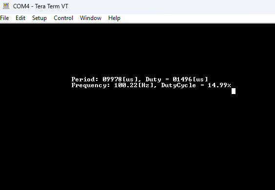
2.4 - Print the results on the serial terminal (USART 2)
-
Print period, frequency, positive width, and duty cycle over
USART 2and display them on Tera Term. -
Try different frequencies and duty cycles and verify that the capture works as intended.
3️⃣ Part B – Input PWM mode (Dual-channel Capture)
Repeat the procedure from part A, this time using two channels (CHANNEL 1 and CHANNEL 2) in Input PWM Mode
3.1 - Configure GPIO alternate function
-
Configure only the
CH1pin (e.g., TIM15_CH1). -
CH2does not need a GPIO configuration
3.2 - Configure the Timer
-
Prescaler so the timer ticks at
1 MHz(1[µs]resolution), same as in Part A. -
Configure
- Channel 1 → TI1, rising edge
- Channel 2 → TI1, falling edge
-
Enable Both Capture Channels, but only enable interrupt for Channel 2 (falling edge),
-
The pulse with can be obtained as
PW = CCR2 - CCR1 -
The period can be obtained by the time distance between two falling edges.
3.3 - Compute frequency and duty cycle
Same formulas as in Part A. Perform these calculations every 250[ms].
- Frequency:
- Duty cycle:
Where:
-
$T_{\mathrm{HIGH}}$ =
positive pulse width -
$T_{\mathrm{PERIOD}}$ =
rising‑to‑rising or falling-to-falling period
3.4 - Print the results on the serial terminal (USART 2)
-
Print period, frequency, positive width, and duty cycle over
USART 2and display on Tera Term. -
Try different frequencies and duty cycles and verify the capture works as intended.
3.5 Questions
-
How is the implementation of Part B more or less efficient than the implementation of Part A? Explain.
-
How can you verify that the timer is only interrupting on falling‑edge captures?
-
Could the program still interrupt on both rising and falling edges? What difference would it make?
4️⃣ Part C - Challenge
-
Using the configuration from part B, what happens when you feed a
10[Hz]signal?. Can the period be detected properly? Explain. -
What is the minimum and maximum frequencies that the input capture could detect using a 16-bit timer and 1[us] ticks?
-
How can we add a fix so the timer could detect frequecnies lower than the minimum capabl;e of detecting at 1[us] ticks?