🧠 Digital Logic Gates: Introduction & Fundamentals
🎯 Learning Objectives
By the end of this lesson, students will be able to:
- Understand the function of basic logic gates
- Interpret truth tables and gate symbols
- Apply gate logic to solve simple digital problems
- Recognize gate behavior in real-world digital systems
🔌 Logic Gates Overview
Logic gates are the building blocks of digital electronics. Each gate performs a specific Boolean function based on one or more inputs and produces a single output.
🧱 The Gates
1. 🔄 Buffer Gate
- Function: Passes the input directly to the output.
- Symbol: Triangle pointing right (no inversion circle).

- Truth Table:
| Input | Output |
|---|---|
| 0 | 0 |
| 1 | 1 |
- Use Case: Signal amplification or delay.
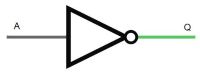
2. 🔁 Inverter (NOT Gate)
- Function: Inverts the input signal.
- Symbol: Triangle with a small circle at the output.
- Truth Table:
| Input | Output |
|---|---|
| 0 | 1 |
| 1 | 0 |
- Use Case: Toggle operations, control logic.
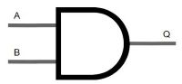
3. 🔗 AND Gate
- Function: Outputs 1 only if all inputs are 1.
- Symbol: Flat-ended D shape.
- Truth Table:
| A | B | Output |
|---|---|---|
| 0 | 0 | 0 |
| 0 | 1 | 0 |
| 1 | 0 | 0 |
| 1 | 1 | 1 |
- Use Case: Conditional logic, safety systems.
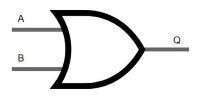
4. 🔀 OR Gate
- Function: Outputs 1 if any input is 1.
- Symbol: Curved shape narrowing to output.
- Truth Table:
| A | B | Output |
|---|---|---|
| 0 | 0 | 0 |
| 0 | 1 | 1 |
| 1 | 0 | 1 |
| 1 | 1 | 1 |
- Use Case: Alarm systems, decision-making logic.
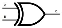
5. ❌ Exclusive OR (XOR) Gate
- Function: Outputs 1 if only one input is 1.
- Symbol: OR gate with an extra curved line at the input.
- Truth Table:
| A | B | Output |
|---|---|---|
| 0 | 0 | 0 |
| 0 | 1 | 1 |
| 1 | 0 | 1 |
| 1 | 1 | 0 |
- Use Case: Parity checks, toggling bits.
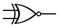
6. ✅ Exclusive NOR (XNOR) Gate
- Function: Outputs 1 if inputs are equal.
- Symbol: XOR gate with inversion circle.
- Truth Table:
| A | B | Output |
|---|---|---|
| 0 | 0 | 1 |
| 0 | 1 | 0 |
| 1 | 0 | 0 |
| 1 | 1 | 1 |
- Use Case: Equality checks, digital comparators.
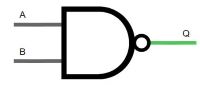
7. 🚫 NAND Gate
- Function: Outputs 0 only if all inputs are 1.
- Symbol: AND gate with inversion circle.
- Truth Table:
| A | B | Output |
|---|---|---|
| 0 | 0 | 1 |
| 0 | 1 | 1 |
| 1 | 0 | 1 |
| 1 | 1 | 0 |
- Use Case: Universal gate (can build any other gate).
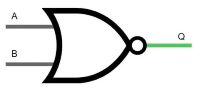
8. 🚷 NOR Gate
- Function: Outputs 1 only if all inputs are 0.
- Symbol: OR gate with inversion circle.
- Truth Table:
| A | B | Output |
|---|---|---|
| 0 | 0 | 1 |
| 0 | 1 | 0 |
| 1 | 0 | 0 |
| 1 | 1 | 0 |
- Use Case: Universal gate, control logic.